INTRODUCTION
Glass components are connected with one
another by flanged joints. All the glass nozzles have special ends known as buttress ends
to fix up a backing flange behind the end and connect the two opposite flanges by bolting
with each other.
Coring usually gives tapered buttress
ends (GARG type) which are backed by a metal flange with matching tapered bore and with a
soft asbestos insert in between to prevent excessive point stresses on the glass surface.
These joints give excellent performance when the glass and metal tapers are perfectly
matched with full concentricity and when the alignment is perfect. In case of sight
imperfection, there is a chance of excessive stresses and breakage of glass neck.
Secondly, because of the taper fit, the glass to flange joint is mechanically locked and
it is difficult to change flanges.
We give another type of end which we call
collared buttress end. This is similar to stub ends used in copper and stainless steel
piping. The collar is backed by an asbestos rope, a metal split ring and a metal backing
flange. This type of joint is very strong and has flexibility in case of slight
misalignment. The overall dimensions of this type of end are kept same as those of tapered
end. Hence it is easy top interchange these types of ends; and even fixing tapered end
with collared end is possible.
The following table gives dimensions of both
the types of buttress ends
| Nomial Bore DN |
25 |
40 |
50 |
80 |
100 |
150 |
225 |
300 |
450 |
600 |
| Outside Diameter D |
33 |
46 |
59 |
87 |
115 |
163 |
238 |
322 |
475 |
640 |
| Inside Diameter D1 |
26.5 |
38.5 |
50 |
76 |
104 |
154 |
229 |
308 |
462 |
622 |
| Collar Diameter D2 |
42.5 |
57.5 |
70 |
99.5 |
133 |
185 |
259 |
341 |
535 |
642 |
TOP
FLANGES
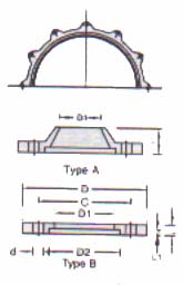
These flanges are used to couple a glass
ends to glass ends or to a below.Backing flanges are made up of cast iron and are used
with inserts.They can normally be supplied in various grades of stainless steel on special
order.
| Cat Ref |
DN |
D |
D1 |
D2 |
C |
N x d |
L |
L1 |
|
| GCF 25 |
25 |
95 |
43 |
51 |
70 |
3 x 7 |
10 |
6 |
| GCF 40 |
40 |
110 |
58 |
66 |
86 |
3 x 9 |
10 |
6 |
| GCF 50 |
50 |
120 |
70 |
81 |
98 |
3 x 9 |
12 |
8 |
| GCF 80 |
80 |
155 |
101 |
112 |
133 |
6 x 9 |
12 |
9 |
| GCF 100 |
100 |
200 |
134 |
148 |
178 |
6 x 9 |
12 |
9 |
| GCF 150 |
150 |
275 |
186 |
196 |
254 |
6 x 9 |
15 |
9 |
| GCF 225 |
225 |
350 |
260 |
282 |
310 |
8 x 11 |
28 |
7 |
| GCF 300 |
300 |
425 |
342 |
363 |
395 |
12 x 11 |
34 |
7 |
| GCF 450 |
450 |
630 |
537 |
557 |
585 |
12 x 14 |
37 |
7 |
| GCF 600 |
600 |
755 |
643 |
690 |
710 |
12 x 14 |
50 |
5 |
TOP
INSERTS
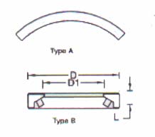
Two types of inserts are used depending upon
the type of buttress ends and the backing flange.
1. Type A : For tapered buttress ends,
asbestos gasket arcs are used for fitting between the tapered end and the flange.
2. Type B : For collared buttress ends,
Cast iron split rings with thin asbestos rope are used & as backing rings between
collar and the flange.
| CAT. REF. |
DN |
D |
D1 |
L |
|
| GCNB 25 |
25 |
50 |
32 |
10 |
| GCNB 40 |
40 |
65 |
48 |
10 |
| GCNB 50 |
50 |
80 |
60 |
10 |
| GCNB 80 |
80 |
110 |
88 |
11 |
| GCNB 100 |
100 |
146 |
117 |
14 |
| GCNB 150 |
150 |
195 |
165 |
14 |
| GCNB 225 |
225 |
280 |
240 |
10 |
| GCNB 300 |
300 |
361 |
324 |
10 |
| GCNB 450 |
450 |
555 |
480 |
18 |
| GCNB 600 |
600 |
684 |
642 |
10 |
TOP
ADAPTOR
FLANGES
These flanges are used for coupling the
glass components with other equipments or pipe lines. For this purpose, the drillings on
the adaptor flanges are as per desired standards namely BS 10 Table E, Table F or ASA 150.
For the flanges, specify as follows.
| CAT REF. |
DN |
H |
D |
 |
| GCFA 1 |
25 |
15 |
115 |
| GCFA 1.5 |
40 |
18 |
150 |
| GCFA 2 |
50 |
21 |
165 |
| GCFA 3 |
80 |
24 |
200 |
| GCFA 4 |
100 |
26 |
220 |
| GCFA 6 |
150 |
26 |
285 |
| GCFA 9 |
225 |
29 |
395 |
| GCFA 12 |
300 |
34 |
445 |
TOP
COMPRESSION
SPRINGS
Compression springs are used to set and
maintain the correct bolt load on standard glass couplings. Standard compression springs
have corrosion resistant coating and are also available in stainless steel.
CORROSION
PROTECTED SPRING STEEL
| CAT. REF. |
DN |
Free Length
L |
Installed Length
L1 |

|
| GDF 6.5 |
15 |
10.1 |
8.1 |
| GDF 8.5 |
25-100 |
14.5 |
11.0 |
| GDF 10.5 |
150-300 |
22.0 |
18.0 |
| GDF 13 |
450-600 |
28.7 |
22.7 |
| GDF 13.5 |
800-1000 |
45.0 |
36.0 |
STAINLESS
STEEL
| CAT. REF. |
DN |
Free Length
L |
Installed Length
L1 |
| GDF 6.5E |
15 |
12.4 |
10.4 |
| GDF 8.5E |
25-100 |
18.0 |
14.5 |
| GDF 10.5E |
150-300 |
28.5 |
24.5 |
| GDF 13E |
450-600 |
37.3 |
31.3 |
TOP
PTFE
"O" RINGS
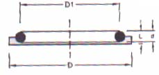
They are used as gaskets and sandwiched
between buttress ends in glass couplings
| CAT. REF. |
DN |
D |
D1 |
d |
L |
|
| GTR 25 |
25 |
62 |
33 |
3 |
5 |
| GTR 40 |
40 |
57 |
48 |
3 |
5 |
| GTR 50 |
50 |
70 |
59 |
3 |
5 |
| GTR 80 |
80 |
100 |
88 |
3 |
5 |
| GTR 100 |
100 |
134 |
119 |
4 |
5 |
| GTR 150 |
150 |
186 |
168 |
4 |
5 |
| GTR 225 |
225 |
260 |
236 |
4 |
5 |
| GTR 300 |
300 |
342 |
318 |
4 |
5 |
| GTR 450 |
450 |
537 |
490 |
6 |
5 |
| GTR 600 |
600 |
686 |
640 |
8 |
10 |
TOP
PTFE
BELLOWS
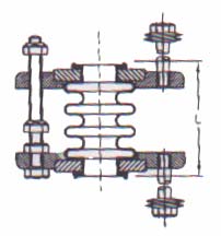
PTFE Bellows are important components in
glass piping. They take care of slight misalignment and thermal expansion as well as
mechanical stresses. They even absorb vibrations. Hence, they are invariably used in
connecting glass components with other non-glass equipments. The PTFE Bellows have built
in 'O' Ring and hence no other gasket is required in the use. They can be supplied with
split rings and flanges with suitable drillings.
| CAT. REF. |
DN |
L |
|
| GFB 25 |
25 |
68 |
| GFB 40 |
40 |
68 |
| GFB 50 |
50 |
68 |
| GFB 80 |
80 |
68 |
| GFB 100 |
100 |
68 |
| GFB 150 |
150 |
68 |
| GFB 225 |
225 |
68 |
| GFB 300 |
300 |
68 |
TOP
PTFE
VACCUM BELLOWS
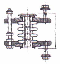
These bellows are made stronger to
withstand vaccum. Inner sleeves are also supplied for these bellows on special order.
| CAT. REF. |
DN |
L |
|
| GFB 80 |
80 |
65 |
| GFB 100 |
100 |
65 |
| GFB 150 |
150 |
65 |
| GFB 225 |
225 |
65 |
| GFB 300 |
300 |
65 |
|


