
|
Home | Profile | Quality | Technical Info | Products | Standard Assemblies | Laboratory Glassware | Glass Jacketed Vessels | Glass Tubes | PTFE Lined Products | PTFE Labware | Plastic Labware | Contact Us |Feedback | Sitemap
Pipeline
Components |
Valves
& Filters | Heat
Exchangers | Vessels
& Stirrers | Column
Components |
Pumps
| Control
| Couplings
| Structure
| Sight
Glasses
|
Standard glass vessels are available in two basic forms: spherical
(available up to 200 litres in capacity) and cylindrical (available up to 200 litres in
capacity). Large spherical vessels are not available but cylindrical vessels with higher
capacity than 200 litres can be supplied to special orders.
All glass vessels have standard flat buttress end connections.
Further details of these are provided in section Technical Information.
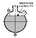
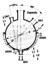
When spherical vessels are used as
Stirring vessels or reboilers, the top branch in generally used for the column or stirrer. The
side branches on standard vessels are generally DN 25, DN 40 or DN 100; DN 25 and DN 40
being at 10° to the vertical (45° on type VSU) and DN 100 being at 45°. The only
exception to this are type VSD spherical vessels which have DN 50, DN 80 and DN 150 side
branches at 90° to the vertical and are used mainly in boiler circulatory systems. The
smaller branches are normally used for such components as thermometer pockets, resistance
thermometer and feed pipes. The DN 100 branches are normally used for charging solids or
for the connection of vapour pipes when the top branch is used for a stirrer. In
application where temperature control is necessary, heating bath and mantles are available
and detailed in this section. In addition, some glass vessels are available with jacket
for close temperature control. If spherical or cylindrical vessels are used in conjunction
with a heating mantle or bath, a longer bottom outlet is required and should be specified when ordering. The VSL
spherical vessels are specifically designed for this purpose. The majority of vessels have DN 40 bottom outlet. For
application where it is necessary to avoid the build-up of solids in this outlet, the
vessel can be fitted with a bottom outlet valve. (See section – Valves & Filters). This
should be specified when ordering. The type RFC valve is an ideal alternative for vessels,
which do not have a sealed-in valve seat. By combining vessels with stirrers and stirrer drives,
an extremely wide range of agitated Stirring equipment options is possible. This fact is
enhanced by the inclusion of PTFE Stirrers
as well as their glass counterparts, thus allowing further options to be considered in the
process design. Vessel/stirrer compatibility tables are detailed in individual stirrer
description. Both spherical & cylindrical vessels can be
supplied with graduations to special order. Standard graduated cylindrical vessels are
shown in this section. For standard flat buttress end connections from DN25 to
DN150, it is possible to achieve a 3° deflection in the joint by using a flexible gasket.
Details of these and all other couplings and gasket can be found in section Couplings. Unless otherwise stated, all dimensions are given in
mm. All vessel capacities are given in liters. For permissible operating conditions, unless otherwise stated in the individual description, please see section Technical Information. |
Spherical Vessels - Type E
Nominal |
Working |
DN |
DN1 |
DN2 |
DN3 |
DN4 |
DN5 |
L |
Cat. Ref. |
 |
50 |
60 |
100 |
225 |
40 |
40 |
100 |
100 |
850 |
GVSE50 |
|
100 |
104 |
150 |
225 |
40 |
40 |
100 |
100 |
940 |
GVSE100 |
|
200 |
206 |
225 |
225 |
40 |
40 |
100 |
100 |
1195 |
GVSE200 |
Nominal and working capacities are in liters.
These vessels have a bottom outlet which accommodates an HEM9 or HES9 immersion heater or a metal heat exchanger of similar dimensions and they are therefore generally used as Stirring vessels.
Nominal |
Working |
DN |
L |
Cat.Ref |
 |
5 |
5 |
40 |
305 |
GVS5A |
|
10 |
11 |
40 |
380 |
GVS10A |
|
20 |
23 |
80 |
450 |
GVS20A |
|
50 |
62 |
100 |
670 |
GVS50A |
|
100 |
110 |
150 |
760 |
GVS100A |
|
200 |
220 |
225 |
1015 |
GVS200A |
These are the basic spherical vessels from which the others are made.
Nominal |
DN |
DN1 |
L |
L1 |
CatRef |
|
5 |
150 |
25 |
460 |
60 |
GVZ5/6 |
|
10 |
150 |
25 |
720 |
60 |
GVZ10/6 |
|
20 |
225 |
25 |
750 |
60 |
GVZ20/9 |
|
30 |
300 |
40 |
635 |
65 |
GVZ30/12 |
|
30 |
300 |
40 |
720 |
150 |
GVZ30/12L |
|
50 |
300 |
40 |
915 |
65 |
GVZ50/12 |
|
50 |
300 |
40 |
1000 |
150 |
GVZ50/12L |
|
100 |
450 |
40 |
890 |
65 |
GVZ100/450 |
|
100 |
450 |
40 |
975 |
150 |
GVZ100/450L |
|
150 |
450 |
40 |
1195 |
65 |
GVZ150/450 |
|
200 |
450 |
40 |
1500 |
65 |
GVZ200/450 |
The nominal capacity is in liters.
Vessels with catalog reference suffixed "L' have longer bottom outlets, DN1, for use with heating mantles and heating baths.
Cylindrical vessels can be used for a wide variety of purposes; for example, Stirring vessels, separator vessels, receivers or feed vessels.
Note :
Cylindrical vessels up to a capacity of 50 liters can generally supported by the upper flange. Vessels of 100 liters capacity and above must be supported from below in a vessel support.
Graduation:
All
these cylindrical vessels can be graduated if required. When ordering please indicate the
graduation required and add the letter G to the catalog reference (e.g. VZG 20/9 graduated
in liters).
Stirring Vessels
Cat Ref |
|
GDVZ10/6 |
GDVZ20/9 |
GDVZ50/12 |
 |
Nominal Capacity |
L |
10 |
20 |
50 |
|
DN |
mm |
150 |
225 |
300 |
|
DN1 |
mm |
25 |
25 |
40 |
|
DN2 |
mm |
25 |
25 |
25 |
|
L |
mm |
720 |
750 |
915 |
|
Pressure in Vessel |
bar. g |
1 |
1 |
0.7 |
|
Temperature In Vessel |
°F |
300 |
300 |
300 |
|
Steam Pressure in Jacket |
bar.g |
0.1 |
0.1 |
0.1 |
|
Liquid Pressure in Jacket |
bar.g |
0.5 |
0.5 |
0.3 |
|
Temperature in Jacket |
°F |
265 |
265 |
265 |
Stirring vessels are used as heated or cooled Stirring vessels. The table above shows the maximum temperatures and pressures recommended for each type.
Cylindrical Vessel Covers Without Center Neck
DN |
DN1 |
PCD |
L |
Type |
CatRef |
|
150 |
40 |
110 |
215 |
A |
GVZA 6 |
|
225 |
40 |
180 |
240 |
B |
GVZA 9 |
Cylindrical Vessel Covers With Center Neck
DN |
DN1 |
DN2 |
PCD |
L |
L1 |
Type |
CatRef |
 |
300 |
80 |
40 |
245 |
280 |
265 |
A |
GVZA12/2 |
|
450 |
80 |
40 |
355 |
375 |
275 |
B |
GVZA450/2 |
|
600 |
100 |
40 |
440 |
400 |
320 |
B |
GVZA600/2 |
The center neck on these vessel covers is generally used with a stirrer
Cylindrical Vessel Covers With Charge Port and Center Neck
DN |
DN1 |
DN2 |
DN3 |
DN4 |
DN5 |
PCD |
L |
L1 |
L2 |
CatRef |
225 |
80 |
80 |
50 |
40 |
25 |
190 |
325 |
225 |
100 |
GVZA9/3 |
300 |
100 |
80 |
80 |
40 |
40 |
245 |
280 |
265 |
90 |
GVZA12/3 |
450 |
150 |
100 |
100 |
40 |
40 |
355 |
350 |
275 |
130 |
GVZA450/3 |
600 |
150 |
100 |
150 |
40 |
40 |
440 |
400 |
320 |
160 |
GVZA600/3 |
|
Cylindrical Vessel Covers With Charge Port but Without Center neck
DN |
DN1 |
DN2 |
DN3 |
DN4 |
DN5 |
R |
R1 |
R2 |
L |
L1 |
L2 |
CatRef |
 |
300 |
100 |
80 |
80 |
40 |
40 |
75 |
115 |
125 |
280 |
265 |
90 |
GVZA12/4 |
|
450 |
150 |
100 |
100 |
40 |
40 |
145 |
160 |
180 |
350 |
275 |
130 |
GVZA450/4 |
|
600 |
150 |
100 |
150 |
40 |
40 |
180 |
180 |
220 |
400 |
320 |
160 |
GVZA600/4 |
These items may be used with off center mounted stirrers which minimize swirling and vortexing effects
Nominal |
Diam |
Square |
Height |
Heating |
Bath |
CatRef |
|
20 |
638 |
486 |
305 |
0.6 |
34 |
GHB20 |
|
50 |
749 |
597 |
457 |
0.6 |
38 |
GHB50 |
|
100 |
902 |
749 |
610 |
0.9 |
57 |
GHB100 |
|
200 |
1054 |
902 |
610 |
0.9 |
57 |
GHB200 |
The nominal capacity is in liters.
This
is a simple cylindrical steel tank with copper steam coils inside it. The drain plug is
1" N.P.T., and the two steam coil connections are 3/4" N.P.T.. A steel ring
wrapped with TFE rope is provided to hold down the vessel and prevent it from floating.
Use
vessels with either a 25 mm or 40 mm diameter neck at the bottom-150 mm long; please
specify which diameter ordering the heating bath tank. The bottom neck of the vessel is
sealed through the tank with a rubber gasket.
Another method of heating and cooling vessels is to use a coil-type immersion heat exchanger.
Heating Bath- Steam or Oil Heated
Nominal Capacity |
d |
DN¹ |
C² |
L |
CatRef
|
CatRef³
|
 |
20
|
490 |
25 |
310 |
240 |
GBDH
20 |
GBDH
20/1.5 |
|
50
|
625 |
25 |
395 |
320 |
GBDH
50 |
GBDH
50/1.5 |
|
100
|
730 |
25 |
585 |
370 |
GBDH
100 |
GBDH
100/1.5 |
|
200
|
910 |
25 |
585 |
455 |
GBDH
200 |
GBDH
200/1.5 |
PN 16
C=
PCD of three support points for vessels with sealed-in valve seat for BAL 1.5
Maximum Steam pressure: 10 bar.g
Heating baths can be used to advantage in applications where the material being handled
would tend to block or stick to the coils type heat exchangers. The stuffing box for the
bottom outlet is specially designed to avoid imposing any stress on the spherical vessel.
Although the standard heating baths are specifically designed for spherical vessels,
similar baths for cylindrical vessels can also be supplied to special order. All these
heating baths can be fitted with suitable temperature control equipment if required.
Note: Heating baths can only be used with vessels having a long bottom outlet, for example type L or vessels with sealed-in seat for bottom outlet valve BAL 1.5
Nominal Capacity |
d |
DN¹ |
C² |
L |
L1 |
L2 |
Loading
kW |
Circuits |
CatRef
|
|
20
|
470 |
40 |
310 |
270 |
315 |
45 |
2.7 |
2 |
GJMD 20 |
|
50
|
610 |
40 |
395 |
330 |
470 |
85 |
4.5 |
3 |
GJMD 50 |
|
100
|
715 |
40 |
585 |
385 |
520 |
85 |
6.6 |
3 |
GJMD
100 |
|
200
|
890 |
40 |
585 |
475 |
610 |
65 |
10.8 |
3 |
GJMD
200 |
DN1 is the bottom outlet of the spherical vessel.
C is the PCD of the three support points.
Heating
mantles provide a positive alternative to steam heating using boilers or immersion
heaters. They run at black heat, transferring the heat to the liquid partly by radiation
and partly by convection.
The heating
elements are closely pitched in a sinusoidal pattern to give an even distribution of heat
and to avoid hot spots. This results in a thermal efficiency exceeding 80%.
Precise
control of heat input is provided by a system of energy regulators and switches built into
the heating mantle circuitry. All heating mantles are fitted with safety cutout
thermostats in order to prevent overheating of the glass vessel.
Type VSL spherical vessels – vessels with sealed-in valve seat for BAL bottom outlet valves are ideal for use with these units.
Hazardous Area Heating Mantles
Nominal Capacity |
d |
DN¹ |
C² |
L |
L1 |
L2 |
Loading kW |
Circuits |
Cat Ref |
|
20 |
470 |
40 |
310 |
270 |
445 |
45 |
1.8 |
1 |
GJFD 20 |
|
50 |
610 |
40 |
395 |
330 |
515 |
85 |
3.2 |
2 |
GJFD 50 |
|
100 |
715 |
40 |
585 |
385 |
565 |
85 |
4.8 |
3 |
GJFD 100 |
|
200 |
890 |
40 |
585 |
475 |
655 |
65 |
6.3 |
3 |
GJFD 200 |
DN1 is the bottom outlet of the spherical vessel.
C is the PCD of the three support points
These mantles are flame
proof and have been specifically designed for use in hazardous areas and include switches
and control geared house in N.K.J, C.M.R.I. certificate No.CMRI/TC/h-954 date- 8.9.95,
temperature classification: T1, group: IIA, and IIB.
Heating elements is flameproof by covering it in magnesium oxide powder and anti corrosive metal INCOLOY 800 tube. The heating element sheath is earth through junction box so that no sparking or short circuit is possible, even in the event of spillage. Metal sheathed heating element produced uniform and black heat. Fiberglass cloth is used to cover the heating element, ceramic insulating blanket, refractory insulator, glass wool etc. used for insulation purpose.
Spherical Vessel Support Rings
Vessel |
D |
PCD |
CatRef
|
|
5
|
175
|
254
|
GVRS5
|
|
10
|
200
|
254
|
GVRS10
|
|
20
|
240
|
310
|
GVRS20
|
This type of ring is used to support the three smallest sizes of spherical vessel. The ring is fitted with a close fitting silicone correct rubber section and has three drilled lugs which correspond with holes in the appropriate support frame. The ring is positioned on three lengths of threaded rod on which it can be adjusted to the correct height.
Vessel |
D |
D1 |
L |
PCD |
CatRef
|
|
20
|
290
|
240
|
50
|
310
|
GVSS20A
|
|
50
|
398
|
328
|
60
|
395
|
GVSS50A
|
|
100
|
475
|
390
|
70
|
515
|
GVSS100A
|
|
200
|
589
|
488
|
80
|
585
|
GVSS200A
|
These holders are used with the larger sizes of spherical vessels. They consist of a metal casing with a felt lining. The lining is shaped to fit the outside of the vessel. The holder is supported on three jacking bolts which are positioned in holes on a support frame. The bolts can be adjusted until the vessel is level and at the right height.
Vessel DN |
D |
D1 |
L |
PCD |
CatRef
|
 |
450
|
375
|
283
|
70
|
395
|
GVZS450A
|
These vessel holders are identical in design and use to the holders for the larger spherical vessels.
Horizontal phase separators are used to continuously separate
immiscible liquids of differing specific gravities. These vessels provide for low
velocities, long residence times and large interface areas between the light and heavy
phases - all factors aiding the separation process. The two phases are independently
drained off at the outlet end. The transparency of borosilicate glass allows visual
inspection of the interface for ease of operation.
DN |
Flow rate total of both phase |
Flow rate of heavy phase for unit with adjustable overflow valve
AOF |
Minimum specific gravity difference at maximum flow rate. |
100 |
100 |
- |
0.05 |
150 |
300 |
600 |
0.05 |
225 |
850 |
900 |
0.1 |
300 |
2200 |
1600 |
0.1 |
450 |
4700 |
3200 |
0.1 |
Horizontal Phase Separators without built-in valve
DN |
DN1 |
DN2 |
DN3 |
DN4 |
L |
L1 |
L2 |
L3 |
L4 |
L5 |
L6 |
L7 |
CatRef
|
100
|
25
|
25
|
25
|
25
|
600
|
150
|
150
|
100
|
100
|
120
|
95 |
360 |
GA4
|
150
|
40
|
25
|
25
|
25
|
1000
|
200
|
500
|
100
|
100
|
140
|
270 |
630 |
GA6
|
225
|
80
|
40
|
40
|
40
|
1650
|
250
|
1000
|
125
|
120
|
180
|
330 |
1170 |
GA9
|
300
|
100
|
50
|
50
|
50
|
2240
|
300
|
1500
|
150
|
150
|
230
|
390 |
1710 |
GA12
|
450 |
150
|
80
|
80
|
80
|
2975
|
375
|
2000
|
180
|
175
|
330
|
525 |
2225 |
GA450
|
|
Horizontal Phase
Separators with Sealed-in overflow valve
for adjustment of the interface level
DN |
DN1 |
DN2 |
DN3 |
DN4 |
DN5 |
L |
L1 |
L2 |
L3 |
L4 |
L5 |
L6 |
L7 |
L8 |
CatRef |
150 |
40 |
25 |
25 |
25 |
25 |
1100 |
200 |
500 |
100 |
100 |
100 |
140 |
270 |
630 |
GAOF6/1 |
225 |
80 |
40 |
40 |
40 |
25 |
1750 |
250 |
1000 |
125 |
100 |
120 |
180 |
330 |
1170 |
GAOF9/1.5 |
300 |
100 |
50 |
50 |
50 |
40 |
2360 |
300 |
1500 |
135 |
120 |
150 |
230 |
390 |
1710 |
GAOF 12/2 |
450 |
150 |
80 |
80 |
80 |
40 |
3100 |
375 |
2000 |
150 |
150 |
175 |
330 |
525 |
2225 |
GAOF450/3 |
Non-standard and intermediate sizes, especially for smaller density differences than those detailed above, can be supplied on request.
|
These cyclones are designed for the separation not only
of droplets from gases and vapors but also of particulate solids from gases. The overall
degree of separation can be as high as 99%, but this figure is governed to a large extent
by the following factors:
Liquid loading of the gas
or vapor.
Solids loading of the
gas.
Droplet or particle size range.
DN |
DN1 |
DN2 |
DN3 |
DN4 |
L |
L1 |
L2 |
L3 |
L4 |
L5 |
CatRef
|
Capacity |
|
100
|
40
|
25
|
80
|
40
|
715
|
560
|
130
|
125
|
35
|
180
|
GCY
4 |
4.3
|
|
150
|
50
|
25
|
100
|
50
|
840
|
655
|
165
|
150
|
55
|
235
|
GCY
6 |
9.7
|
|
225
|
80
|
25
|
150
|
80
|
1120
|
915
|
225
|
200
|
75
|
320
|
GCY
9 |
29.6
|
|
300
|
100
|
25
|
150
|
100
|
1425
|
1225
|
285
|
275
|
100
|
405
|
GCY
12 |
69.4
|
The following are examples of limiting droplet
diameters for the standard air/water system (at ambient temperature) with a velocity in
the dip pipe of 15 m/sec:
Approx. 2.5 m for
the CY 4 and CY 6 cyclones.
Approx. 3.5 m for the CY 9 and CY 12 cyclones.
The pressure drop in these cases is in the region of
250 to 300 mm water gauge.
The complete cyclone consists of:
1 glass body
1 dip pipe
1 coupling with gasket
DN |
DN1 |
d |
L |
L1 |
CatRef
|
|
40 |
25
|
25
|
100
|
115
|
GDP100
|
|
40
|
25
|
25
|
330
|
115
|
GDP330
|
|
40
|
25
|
25
|
450
|
115
|
GDP450
|
|
40
|
25
|
25
|
510
|
115
|
GDP510 |
|
40
|
25
|
25
|
635
|
115
|
GDP635 |
|
40
|
25
|
25
|
750
|
115
|
GDP750 |
|
40
|
25
|
25
|
850
|
115
|
GDP850 |
|
40
|
25
|
25
|