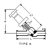
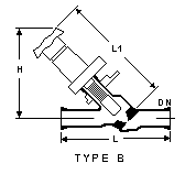
Straight Through Valves
DN
(mm) |
L
(mm) |
L1
(mm) |
H
(mm) |
Bar.g |
TYPE |
Cat Ref |
|
25 |
175 |
190 |
160 |
3.0 |
A + B |
GPV1 |
40 |
225 |
245 |
190 |
3.0 |
A + B |
GPV1.5 |
50 |
300 |
275 |
195 |
2.0 |
A + B |
GPV2 |
80 |
375 |
400 |
300 |
1.5 |
A + B |
GPV3 |
100 |
575 |
580 |
400 |
1.0 |
A + B |
GPV4 |
150 |
600 |
725 |
500 |
1.0 |
A + B |
GPV6A |
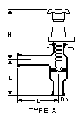
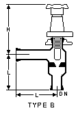
Top
Angle
Valves
DN
(mm) |
L
(mm) |
H
(mm) |
Bar.G |
Type |
Cat Ref |
|
25 |
100 |
160 |
3.0 |
A + B |
GPVE1A |
40 |
150 |
190 |
3.0 |
A + B |
GPVE1.5 |
50 |
150 |
200 |
2.0 |
A + B |
GPVE2 |
80 |
200 |
285 |
1.5 |
A + B |
GPVE3A |
100 |
250 |
370 |
1.0 |
A + B |
GPVE4 |
150 |
250 |
455 |
1.0 |
A + B |
GPVE6A |
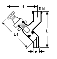
Top
Drain
Valve
DN
(mm) |
d
(mm) |
L
(mm) |
L1
(mm) |
H
(mm) |
Bar.G |
Cat Ref |
|
25 |
18 |
140 |
100 |
90 |
3.0 |
GPV1/58 |
40 |
18 |
150 |
100 |
90 |
3.0 |
GPV1.5/58 |
40 |
27.5 |
200 |
190 |
160 |
3.0 |
GPV1.5/1 |
Top
Vent
Valve
DN
(mm) |
d
(mm) |
L
(mm) |
Bar.g |
Cat Ref |

|
25 |
10 |
120 |
3.0 |
GPVL1 |
40 |
10 |
125 |
3.0 |
GPVL1.5 |
Top
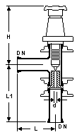
Hand Control Valve
DN
(mm) |
d
(mm) |
L
(mm) |
L1
(mm) |
H
(mm) |
Bar.g |
CV |
Cat Ref |
|
25 |
7 |
100 |
170 |
165 |
3.5 |
1.2 |
GPRV1/1/2 |
25 |
10 |
100 |
170 |
165 |
3.5 |
2.9 |
GPRV1/2.5/2 |
25 |
16 |
100 |
170 |
165 |
3.5 |
7.3 |
GPRV1/6.3/2 |
40 |
25 |
150 |
185 |
175 |
3.0 |
18 |
GPRV1.5/16/2 |
50 |
40 |
150 |
195 |
185 |
2.0 |
46 |
GPRV2/40/2 |
CV values are in gpm with a 1 psi
pressure drop, valve fully opened.
These valves are used to obtain a fine
variation in flow rate. They can be used with both liquids and gasses and give accurate
linear control. If required, a pneumatic actuator can be substituted for the handwheel and
bonnet assembly.
Top
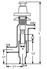
Adjustable Overflow Valve
DN (mm) |
DN1 (mm) |
d (mm) |
L (mm) |
L1 (mm) |
L2 (mm) |
L3 (mm) |
L/H |
Cat Ref |
|
25 |
15 |
25 |
420 |
100 |
165 |
50 |
600 |
GOF1 |
40 |
15 |
25 |
600 |
150 |
265 |
90 |
900 |
GOF1.5A |
50 |
15 |
35 |
610 |
150 |
270 |
90 |
1600 |
GOF2 |
80 |
15 |
60 |
760 |
200 |
335 |
120 |
3200 |
GOF3A |
The figure in liters/hour (L/H) is the
maximum flow through the valve.
These valves provide a means of
externally adjusting the level inside a vessel. They are ideal for use with liquid
separators or liquid-liquid extractors. The lower end of the PTFE bellows is in the form
of a tube of accurately machined external diameter, which fits inside a precision bore
glass tube. Its position can adjusted within
given limits (L3) to set the required overflow level. In applications where the system is
nor self venting via the overflow line, a vent line can be connected to the DN15 nozzle.
Top
Pressure
Relief Valve
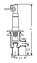
Two types of
pressure relief valve can be supplied: weight operated or springs operated. Both are
constructed of glass and PTFE, without glands. Sealing of moving parts is effected by a
PTFE bellows.
The valves
are designed to meet the requirements of the German Technical Control Association (TUV)
and can be supplied complete with TUV certificate, if required.
The maximum
recommended operating temperature is 150° C and a range of pressures, as indicated below
can be accommodated. Please not that a change in the setting of the blow-off pressure
invalidates the original TUV certification. Both types of pressure relief valves should be
installed with the spindle vertical and adequate support should be given.
Since these
are special order items, when ordering please specify the following:
Catalog reference
Pressure range
Blow-off pressure
Top
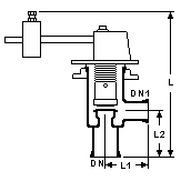
Weight-Operated
Pressure Relief Valves
DN (mm) |
DN1 (mm) |
d (mm) |
L (mm) |
L1 (mm) |
L2 (mm) |
Cat Ref |
|
50 |
40 |
27 |
375 |
100 |
125 |
GSVG1/2/1.5 |
80 |
80 |
38 |
395 |
125 |
150 |
GSVG1.5/3/3 |
Pressure ranges available (bar.g):
0.2 -- 0.27
0.25 -- 0.4
0.3 -- 0.6
0.5 -- 1.1
0.9 -- 1.4
1.5 -- 2.2
Top
Spring-Operated Pressure Relief Valves
DN (mm) |
DN1 (mm) |
d (mm) |
L (mm) |
L1 (mm) |
L2 (mm) |
Cat Ref |
|
50 |
40 |
27 |
515 |
100 |
125 |
GSVF1/2/1.5 |
80 |
80 |
38 |
570 |
125 |
150 |
GSVF1.5/3/3 |
Pressure ranges available (bar.g):
0.5 -- 0.7
0.8 -- 1.3
1.4 -- 2.0
2.1 -- 2.9
3.0 -- 3.5
Top
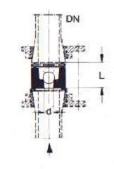
Ball Type Non-Return Valves
These valves are for use only in vertical pipelines. Like glass spacers, they are
fitted between standard buttress end components using longer coupling bolts.
Ball-type non-return valves are supplied complete with glass body, glass ball and
PTFE retaining plate.
DN
(mm) |
d
(mm) |
L
(mm) |
Cat Ref |
|
25 |
10 |
25 |
GNRD 1 |
40 |
15 |
33 |
GNRD 1.5 |
50 |
19 |
41 |
GNRD 2 |
80 |
30 |
65 |
GNRD 3 |
Top
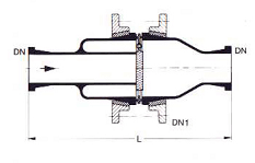
Flap Type Non-Return Valves
Flap-type
non-return valves can be installed in both vertical and horizontal pipelines. The flap is
manufactured from PTFE and is mounted on a tantalum hinge to ensure maximum corrosion
resistance.
DN(mm) |
DN1 (mm) |
L(mm) |
Cat Ref |
|
25 |
50 |
225 |
GRK 1 |
40 |
80 |
275 |
G
RK 1.5 |
50 |
100 |
325 |
GRK 2 |
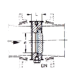
These larger sizes of flap –type
non-return valve are, like NRD type non-return valves, fitted between standard buttress
end components using longer coupling bolts. They can be used in both vertical and
horizontal pipelines. As they are manufactured from PTFE, no gasket is required on either
side of the valve between the PTFE face and the standard glass buttress end. RKP type
non-return valves incorporate a tantalum hinge and are supplied complete.
DN
(mm) |
d
(mm) |
L
(mm) |
Cat Ref |
 |
80 |
55 |
24 |
GRKP 3 |
100 |
82 |
24 |
GRKP 4 |
150 |
125 |
24 |
GRKP 6 |
Top
Bottom Outlet Valves
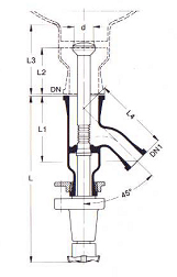
Type BAS and BAL bottom outlet valves are designed specifically for use with such
types of glass items, which have an integral glass seat sealed into the bottom outlet.
The position of the valve seat is such that it reduces the accumulation of solids
in the vessel or drain neck.
Valve seats can be sealed into either spherical or cylinderical vessels as per
requirement.
DN
(mm) |
DN1
(mm) |
D
(mm) |
L
(mm) |
L1
(mm) |
L2
(mm) |
L3
(mm) |
L4
(mm) |
Cat Ref |
 |
40 |
25 |
30 |
270 |
105 |
75 |
110 |
120 |
GBAS 1.5 |
40 |
25 |
30 |
270 |
105 |
155 |
190 |
120 |
GBAL 1.5 |
Bottom
Outlet Valves
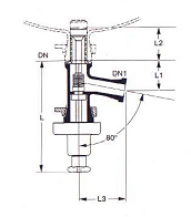
Unlike type BAS and BAL bottom outlet valves shown above, the type RFC bottom
outlet valve is designed for use with spherical and cylindrical vessels which do not have
any integral glass seat sealed into the bottom outlet.
DN
(mm) |
DN1 (mm) |
L
(mm) |
L1
(mm) |
L2
(mm) |
L3
(mm) |
Cat Ref |
|
40 |
25 |
240 |
72 |
65 |
100 |
GRFC 1.5 |
Top
Diaphragm Valves
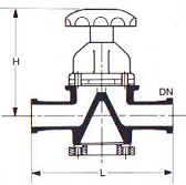
Diaphragm valves re of conventional basic design. They are glandless and the PTFE
diaphragm provides a fine seal with the integral glass weir when the valve is closed.
The maximum continuous operating temperature is 120°C and the maximum thermal
shock is 100°C.
DN(mm) |
L(mm) |
H(mm) |
Cat Ref |
|
25 |
175 |
175 |
GSV 1 |
40 |
200 |
175 |
GSV 1.5 |
Top
|

