|
Composed completely of glass, coil heat exchangers are
typically used as vapor condensers and liquid coolers. They are usually designed and
installed as an integral part of a vertical column. To provide a reliable corrosion
resistant internal seal, the coil battery is sealed to the jacket, creating a single unit.
Boilers and immersion heaters are also available in this all-glass coil design.
Other Designs
We also offer glass cascade coolers, bayonet and
jacketed-type heat exchangers. For further information on these special application
models, please contact us.
Shell & Tube Heat Exchangers
We also offer a wide range of shell and tube heat exchangers
ranging from 13.5 to 505 sq. ft., all capable of modular expansion. For further
information on these units go to the heat exchanger page, or contact us.
Technical Data
Heat Transfer in Condensers
The heat transferred in coil condensers con be considered
generally as 55 Btu/hr-ft2-°F for any unit. This figure may vary from 10 to 72
Btu/hr-ft2-°F depending on the fluids involved and the operating conditions.
Jacket Side |
Vapor to be
condensed |
Liquid to be
cooled |
Gas To be
cooled |
Coil Side |
Cooling Water |
Cooling Water |
Cooling Water |
Heat Transfer
Coefficient
BTU/hr. - ft2 - °F |
50 |
50 |
50 |
The heat transfer coefficient also varies with the size
of the condenser. The following table gives an indication of the performance of condensers
at atmospheric pressure, using water as a coolant in the coils (inlet temperature 68 F)
and steam condensing in the jackets. These figures do not show the maximum performance of
the units but are a general indication of typical working conditions.
Condenser
Catalog
Reference |
Surface
Area
ft2 |
Water
Flow Rate
lbs/hr |
Steam
Condensed
lbs/hr |
 |
GHE1.5 |
2 |
1540 |
15 |
GHE2 |
3.5 |
2200 |
25 |
GHE3 |
3.5 |
2200 |
25 |
GHE4 |
5 |
3300 |
40 |
GHE6/10 |
10 |
3500 |
70 |
GHE6/15 |
15 |
3300 |
110 |
GHEU9A |
25 |
6600 |
198 |
GHEU12/25 |
25 |
6000 |
175 |
GHEU12/40 |
40 |
10400 |
282 |
GHEU450/60 |
60 |
11000 |
435 |
GHEU450/80 |
80 |
9300 |
585 |
GHEA600 |
120 |
14300 |
850 |
|
Applications
Coil heat exchangers are an all-glass design. There are
no internal sealing problems, as the coil is welded into the jacket forming a one-piece
unit. This design is a practical means of packing a large amount of heat transfer surface
into a small volume.
Coil Condensers are used in three general Applications
| Vapor inlet at Bottom |
Vapor inlet at Top |
Liquid--Liquid Exchange |
· Coolant inside the coils.
· Condensate falls against the rising vapor and exits at its boiling point. |
· Coolant inside the coils.
· Condensate exits at the bottom at temperatures below its boiling point, depending on
surface area of the condenser and flow rate of the coolant. |
· Coolant inside the coils.
· Hot liquid in shell flows countercurrently to coolant.
· Cooled liquid exits at top of unit. |
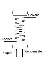
|
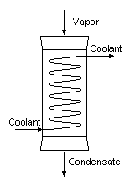
|
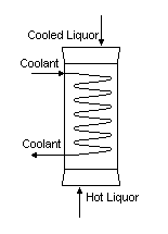
|
Notes on the use of coil type condensers
- Condensers should never be used without an adequate flow
of coolant through the coils. Do not allow the coolant to become heated to boiling point.
- Condensers should never be used with steam in the coil.
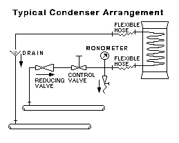
- Take care to arrange the coolant supply in such a way as
to avoid water hammer. Be certain that there is a uniform, continuous supply of coolant.
(For HE 600 condensers, the fitting of an anti-water hammer device is recommended.)
- Coolant control valves should always be turned on and off
slowly, particularly when air is present in the line. Coolant should be allowed to drain
freely to a point as close as practicable to the heat exchanger. Brine in a closed circuit
can be used as coolant provided that suitable precautions against hammer are taken.
- We recommend a maximum gauge pressure of 40 psig in the
coils.
- Adequate flexible hose should be used for connecting the
condenser to the water main to assure that stresses are not transmitted to the glass.
- If a condenser is to be out of service for a period of
time. drain the coils. In winter suitable precautions should be taken to prevent freezing
of any water remaining after draining.
- Condensers can be mounted in a series to provide larger
surface areas.
Note: allowing a minimum pressure drop of 30 psi
(2.1 bar) will result in the most efficient overall heat transfer.
Coil Condensers, 1
| Catalog Reference |
GHE 1.5 |
GHE 2 |
GHE 3 |
GHE 4 |
GHE 6/10 |
GHE 6/15 |
GHEU 9A |
| Heat Transfer Area |
ft2 |
2 |
3.5 |
3.5 |
5 |
10 |
15 |
25 |
| L |
mm |
610 |
610 |
610 |
610 |
610 |
840 |
790 |
| L1 |
mm |
85 |
90 |
90 |
120 |
150 |
150 |
180 |
| L2 |
mm |
100 |
95 |
95 |
80 |
100 |
100 |
125 |
| DN |
mm |
40 |
50 |
80 |
100 |
150 |
150 |
225 |
| DN1 |
mm |
|
|
|
|
25 |
25 |
25 |
| d |
mm |
16 |
16 |
16 |
19 |
|
|
|
| |
| Weight Empty |
lb. |
2 |
3 |
4 |
10 |
15 |
22 |
35 |
| Weight Full |
lb. |
3 |
4 1/2 |
5 |
12 |
21 |
31 |
51 |
| Shell Capacity |
gal. |
0.3 |
0.4 |
0.5 |
1.2 |
2.4 |
2.9 |
5.3 |
| Maximum Cooling Water Rate |
gal./hr. |
200 |
340 |
340 |
720 |
720 |
480 |
940 |
| Operating Temperatures |
oF |
300°F max/min - above collant's freezing
point |
| Maximum Thermal Shock |
oF |
216 |
| Max. Working Pressure-Shell |
psig |
50 |
40 |
30 |
25 |
20 |
20 |
11 |
| Max. Working Pressure-Coil |
psig |
40 |
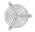 |
All 3-outlet coil units have tubes spaced equidistant
from the face to the center of the nozzle (120° spacing) |
Coil Condensers, 2
| Catalog Reference |
GHEU 12/25 |
GHEU 12/40 |
GHEU 450/60 |
GHEU 450/80 |
GHE 600 |
| Heat Transfer Area |
ft2 |
25 |
40 |
60 |
80 |
120 |
| L |
mm |
610 |
900 |
760 |
900 |
1250 |
| L1 |
mm |
250 |
250 |
350 |
350 |
485 |
| L2 |
mm |
125 |
125 |
150 |
150 |
300 |
| DN |
mm |
300 |
300 |
450 |
450 |
600 |
| DN1 |
mm |
25 |
25 |
40 |
40 |
50 |
| |
| Weight Empty |
lb. |
46 |
66 |
100 |
120 |
270 |
| Weight Full |
lb. |
64 |
95 |
134 |
163 |
381 |
| Shell Capacity |
gal. |
10 |
10.6 |
26.4 |
28.2 |
70 |
| Maximum Cooling Water Rate |
gal./hr. |
720 |
1532 |
1532 |
1300 |
1800 |
| Operating Temperatures |
oF |
300°F max/min -
above collant's freezing point |
| Maximum Thermal Shock |
oF |
216 |
| Max. Working Pressure-Shell |
psig |
8 |
8 |
6 |
6 |
4 |
| Max. Working Pressure-Coil |
psig |
40 |
TOP
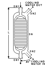
DN
(mm) |
DN1
(mm) |
DN2
(mm) |
L
(mm) |
*
(psig) |
Cooling
Surface
(ft2) |
CatRef |
 |
100 |
25 |
25 |
550 |
35 |
3.5 |
GHEF1/3 |
150 |
25 |
25 |
550 |
25 |
5 |
GHEF1/5 |
150 |
25 |
25 |
750 |
25 |
10 |
GHEF1/10 |
Maximum operating pressure in coil battery
is 30 psig.
* - Maximum operating pressure in cooler jacket |
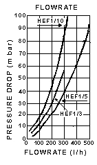
Flowrates through the units depend on feed height. Cooling
water temperature - approximately 64 °F
|
HEF product coolers are
general purpose coolers used, typically, for the cooling of products from distillation
columns.
The coolers can be connected directly to the
product outlet of the column by means of DN1. The product then flows from the top to the
bottom of the unit through the coil battery across which the cooling water flows counter
currently from bottom to |
TOP
immersion heat exchangers are used to control exothermic
reactions in glass vessels. In most applications cooling water is used in the coils, but
they can also be used with steam. In the latter case, the coils must always be completely
immersed in the liquid
The HEM 6 is used in our type R spherical vessels and the
HEM 9 in type E vessels. They can also be used in cylindrical vessels with special 6"
or 9" bottom outlets.
The HEM 9 has a central hole through the coil to which
the extended type stirrer shaft can be fitted to provide thorough mixing action.
Heat Transfer
These values may be used to approximate the overall heat
transfer coefficients and the maximum allowable thermal shock for both the HEM 6 and HEM
9.
| |
Heat Transfer Co efficient
(Btu/hr - ft2 - °F) |
Maximum
Thermal
Shock |
| Cooling, with agitation |
40 - 50 |
125°F |
| Cooling, without agitation |
20 - 30 |
180°F |
| Heating, with agitation |
60 - 70 |
105°F |
| Heating, without agitation |
40 - 50 |
125°F |
Immersion Heaters
| Catalog Reference |
GHEM 6 |
GHEM 9 |
| Heat Transfer Area |
ft2 |
5 |
7 |
| L |
mm |
230 |
275 |
| L1 |
mm |
330 |
205 |
| DN |
mm |
150 |
225 |
| DN1 |
mm |
40 |
40 |
| DN2 |
mm |
25 |
25 |
| d |
mm |
145 |
210 |
| Water flow rate at 30 psig* |
gal./hr. |
357 |
542 |
| Operating Temperatures |
°F |
300°F max/min - above media's freezing
point |
| Maximum Pressure in the coil |
psig |
50 |
* through coils
TOP
Boiler
Catalog
Reference |
Surface
Area
ft2 |
Steam
Pressure
psig |
Water Evaporated
lbs/hr |
GHEB4 |
1.5 |
15 |
4.2 |
50 |
10 |
GHEB6 |
5 |
15 |
14.3 |
50 |
33 |
GHEB9 |
15 |
15 |
42 |
50 |
99 |
GHEB4/4 |
1.5 |
15 |
4.2 |
50 |
10 |
GHEB6/6 |
5 |
15 |
14.3 |
50 |
33 |
GHEB9/9 |
13 |
15 |
31 |
50 |
99 |
GHEB12/12 |
20 |
50 |
123 |
GHEB450 |
45 |
50 |
198 |
Heat Transfer in Boilers
The overall heat transfer coefficient for any 4",
6", 9" or 12" unit is generally about 70 Btu/hr-ft2-°F. This is based on
50 psig steam pressure in the coils, although it declines proportionately at lower
pressures. The heat transferred for the 18" unit is approximately 54 Btu/hr-ft2-°F.
The table shows representative performance data of
boilers, indicating the amount of water evaporated at atmospheric pressure, with steam in
the coils at various pressures.
If the feed is cold, the evaporation rate will be
approximately 85% of the figures shown.
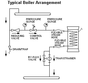 |
Notes on the use of coil type boilers
To avoid the possibility of steam hammer,
the steam main should be adequately trapped.
To clear the line of the very heavy
condensate flow produced on startup, bypass valves must be fitted around the trap on the
coil outlet.
The control valve and pressure gauge
should be near the heat exchanger.
Flexible hose must be used on the coil
inlet and outlet, and these hoses should have sufficient fall to avoid collection of
condensate.
Boiler type heat exchangers should not be
fitted to the bottom of flasks or columns. They are designed to be mounted on an external
circulatory loop. This assures a rapid unidirectional flow across the heating surface,
which improves the heat transfer performance and promotes smooth operation.
On startup, the steam should be admitted
positively and progressively to the coil/battery to remove the condensate as it is formed.
The bypass valve should be left open until a uniform flow of condensate and steam is being
vented.
The steam pressure should always be
adequate to assure effective and smooth condensate removal. This pressure will vary
according to conditions of use and size of heat exchanger. For example, with the HEB12/12
and HEB450 a minimum pressure of 30 psig will probably be required.
The maximum recommended inlet steam
pressure for all boilers is 50 psig.
|
Boilers, 1
| Catalog Reference |
GHEB 4 |
GHEB 6 |
GHEB 9 |
| Heat Transfer Area |
ft2 |
1.5 |
5 |
15 |
| L |
mm |
380 |
455 |
710 |
| L1 |
mm |
125 |
150 |
180 |
| L2 |
mm |
100 |
90 |
140 |
| DN |
mm |
100 |
150 |
225 |
| DN1 |
mm |
25 |
40 |
40 |
| DN2 |
mm |
25 |
25 |
25 |
| |
| Weight Empty |
lb. |
5 |
9 |
22 |
| Shell Capacity |
gal. |
0.7 |
1.2 |
4.5 |
| Coil Capicity |
gal. |
0.1 |
0.4 |
1.2 |
| Free Cross Sectional Area |
in.2 |
6.3 |
8 |
23 |
| Operating Temperatures |
°F |
300 °F max./min.- above media's freezing
point |
| Maximum Thermal Shock |
°F |
216 |
| Max. Working Pressure - Shell |
psig. |
25 |
20 |
11 |
| Max. Working Pressure - Coil |
psig. |
50 |
| Min. Working Pressure - Shell |
psig. |
Full Vacuum |
| Min. Working Pressure - Coil |
psig. |
15 |
Boilers, 2
| Catalog Reference |
GHEB 4/4 |
GHEB 6/6 |
GHEB 9/9 |
GHEB 12/12 |
GHEB 450 |
| Heat Transfer Area |
ft2 |
1.5 |
5 |
13 |
20 |
45 |
| L |
mm |
405 |
510 |
710 |
700 |
915 |
| L1 |
mm |
125 |
150 |
180 |
215 |
325 |
| L2 |
mm |
100 |
100 |
100 |
135 |
125 |
| L3 |
mm |
|
|
|
135 |
140 |
| L4 |
mm |
|
|
|
270 |
350 |
| DN |
mm |
100 |
150 |
225 |
300 |
450 |
| DN1 |
mm |
25 |
25 |
25 |
25 |
40 |
| DN2 |
mm |
|
|
|
25 |
25 |
| |
| Weight Empty |
lb. |
7 |
14 |
33 |
46 |
123 |
| Shell Capacity |
gal. |
0.9 |
2.0 |
5.5 |
11.2 |
32.2 |
| Coil Capicity |
gal. |
0.1 |
0.4 |
1.2 |
1.3 |
6.1 |
| Free Cross Sectional Area |
in.2 |
6.3 |
8 |
30 |
51 |
119 |
| Operating Temperatures |
°F |
300 °F max./min.- above media's freezing
point |
| Maximum Thermal Shock |
°F |
216 |
| Max. Working Pressure - Shell |
psig. |
25 |
20 |
11 |
8 |
6 |
| Max. Working Pressure - Coil |
psig. |
50 |
| Min. Working Pressure - Shell |
psig. |
Full Vacuum |
| Min. Working Pressure - Coil |
psig. |
15 |
30 |
30 |
TOP
Type of
Service |
Flange Plate Drilling
(mm) |
NPT Size of Male Hose
Fitting (in.) |
CatRef |
 |
Water |
25 |
3/4 |
GWHA1/0.75 |
Water |
40 |
1 |
GWHA1.5/1 |
Water |
50 |
1 1/2 |
GWHA2/1.5 |
Steam |
25 |
3/4 |
GSHA1/0.75 |
Steam |
40 |
1 |
GSHA1.5/1 |
|
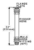
Use these flexible hose assemblies to
connect glass heat exchangers to metal service water and steam piping. Assemblies come
with flange plate drilled to mate with wither ("86" ) or
("72" ) flange; a section of rubber hose to meet the service requirement; a
male, threaded end fitting (NPT) to mate with standard threaded metal pipe; and suitable
connectors.
|

